Pump inside the torso
Design review for the hardware build. Written on 13 October 2026.
The team wants the pump inside the torso, for a lower centre of mass and better balance. The reservoir is ours to design, and we can 3D print it. This article proposes two printed tanks, R1 and R2, gives their CAD files, and compares them in MuJoCo with the earlier concepts A_real (water gun on the pan-tilt) and B_real (backpack with a 12 V diaphragm pump).
Summary
- The pump weighs 33 g. The backpack pump weighed 570 g. So the pump position hardly matters for balance. The water decides it.
- The lower torso is full: the battery and the mini PC fill it. A tank fits in two places: above the mini PC (R1, inside the torso) and on the torso sides above the hips (R2).
- Both options give the lowest robot centre of mass of all our concepts: 0.410 to 0.413 m, against 0.425 m for A_real and 0.429 m for B_real.
- The official walking policy walks with R1 and R2 as well as with the bare robot. It survives pushes about as well as with A_real, and better than with the full backpack.
- The water of R2 sits 10 cm lower than in R1, but the robot centre of mass moves only 3 mm. In the simulation, R1 and R2 balance almost the same.
- This pump gives a weak jet: about 5 to 6.6 m/s with a 1.0 to 1.5 mm nozzle. The robot must get within about 2 m of the fire.
- Recommendation: R1. It is the only option where the pump can sit inside the torso, below the water. Its cost is water above the mini PC.
| Option | Water | Add-on mass, full | Robot CoM height | One-leg pitch torque | Walk speed for 0.30 m/s | Backward push, walking |
|---|---|---|---|---|---|---|
| A_real: gun on the pan-tilt | ≈ 0.45 L | 1.54 kg | 0.425 m | 5.2 Nm | 0.29 m/s | 7.9 N s |
| B_real: backpack | 0.95 L | 2.76 kg | 0.429 m | 3.9 Nm | 0.20 m/s | 4.5 N s |
| R1: tank inside the torso | 0.63 L | 1.65 kg | 0.413 m | 5.7 Nm | 0.30 m/s | 7.9 N s |
| R2: side tanks | 0.73 L | 1.92 kg | 0.410 m | 5.8 Nm | 0.29 m/s | 9.8 N s |
Free space in the torso tested in simulation
We measured the torso mesh of the Berkeley robot. Positions are in mm in the robot frame: x forward, y left, z up from the floor. The top face of the torso frame (the 2020 top rails) is at z = 791. The right column gives the depth under that top face, which is easier to measure on the robot.
| Region | Position (mm) | Depth under the frame top (mm) | Content |
|---|---|---|---|
| Battery (6S LiPo) | x −30 to 33, y −66 to 89, z 583 to 633 | 158 to 208 | Low in the torso. Its end sticks out of the left side to y = 89. |
| Mini PC | x −52 to 51, y ±58, z 639 to 679 | 112 to 152 | On the front and rear shelves. |
| USB board | x 14 to 40, y ±67, z 685 to 711 | 80 to 106 | Front, above the PC. |
| Shoulder brackets | |y| ≥ 66.7, z 681 to 791 | 0 to 110 | Both sides of the upper torso. |
| Pan base of the ST3215 pan-tilt | x −78 to 2, y ±40, z 762 to 791 | 0 to 29 | Hangs under the deck. |
| Free: upper torso | x ±48 (±62 between the posts), y ±63, z 712 to 786 | 5 to 79 | R1 goes here. |
| Free: torso sides | |y| 77 to 124, x ±66, z 590 to 678 | 113 to 201 | R2 goes here. Above the hip motors (top at z 581), under the shoulder brackets. |
The gaps beside the battery are 17 mm wide, and the pump is 25 mm. So no tank and no pump fits low inside the torso.
Pump
| Item | Value |
|---|---|
| Model | TCS Micropumps M400K-V, brushless centrifugal, parallel ports for 3.2 mm bore tubing |
| Size, mass | 40 × 26 × 25 mm, 32 to 34 g |
| At 12 V | 5.8 W (about 0.5 A), 380 mbar maximum pressure, 1150 mL/min free flow |
| At 6 V | 1.2 W, 86 mbar, 500 mL/min |
| Protection | IP45 standard, IP67 waterproof version |
| Priming | Not self-priming. The “-SUB” version is the self-priming, submersible one. |
A centrifugal pump cannot pull water up into itself. It must sit below the water, so that water flows into it by gravity. This rule decides where the pump can go.
Tank options
R1: tank inside the torso planned
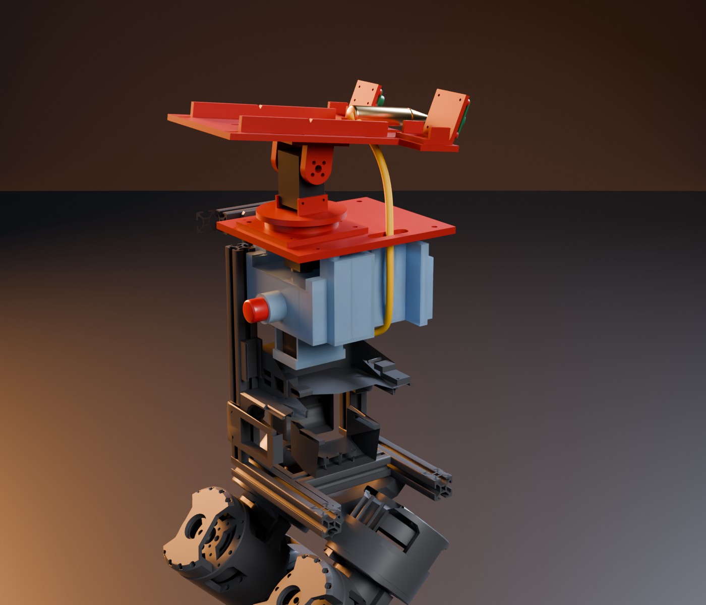
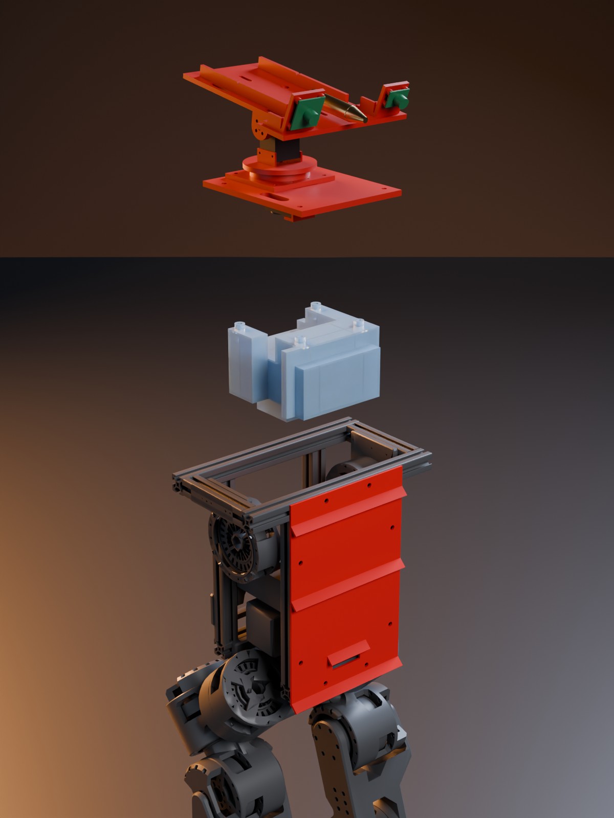
- The tank fills the free upper torso: x ±48 mm and y ±63 mm, plus bays to x ±62 mm between the posts. Its floor is 77 mm and its top 5 mm under the frame top.
- Notches leave room for the pan base and for a cable and hose channel under the deck slot (x −8 to 40, y −70 to −42).
- The tank holds 0.632 L. It has 3 baffles across x and 2 across y, 2 mm thick, with a window in the middle and drain slots at the floor.
- The tank hangs from the pan-tilt deck. The R1 deck is the deck of the pan-tilt module with four more M4 holes. Four M4 screws go through the deck into heat-set inserts in closed pillars on the tank top.
- The pump hangs under the tank floor in a drip tray that is part of the tank print. The tray floor is 2 mm over the mini PC lid in the CAD. A 6 mm drain hole in the tray takes a tube out of the torso.
- The outlet is an M5 thread in the tank floor for a brass hose barb. A short tube loop goes to the pump inlet.
- The fill neck points backward through the rear face, between the rear posts (bore 19 mm). A silicone stopper with a small vent hole closes it.
R2: side tanks planned
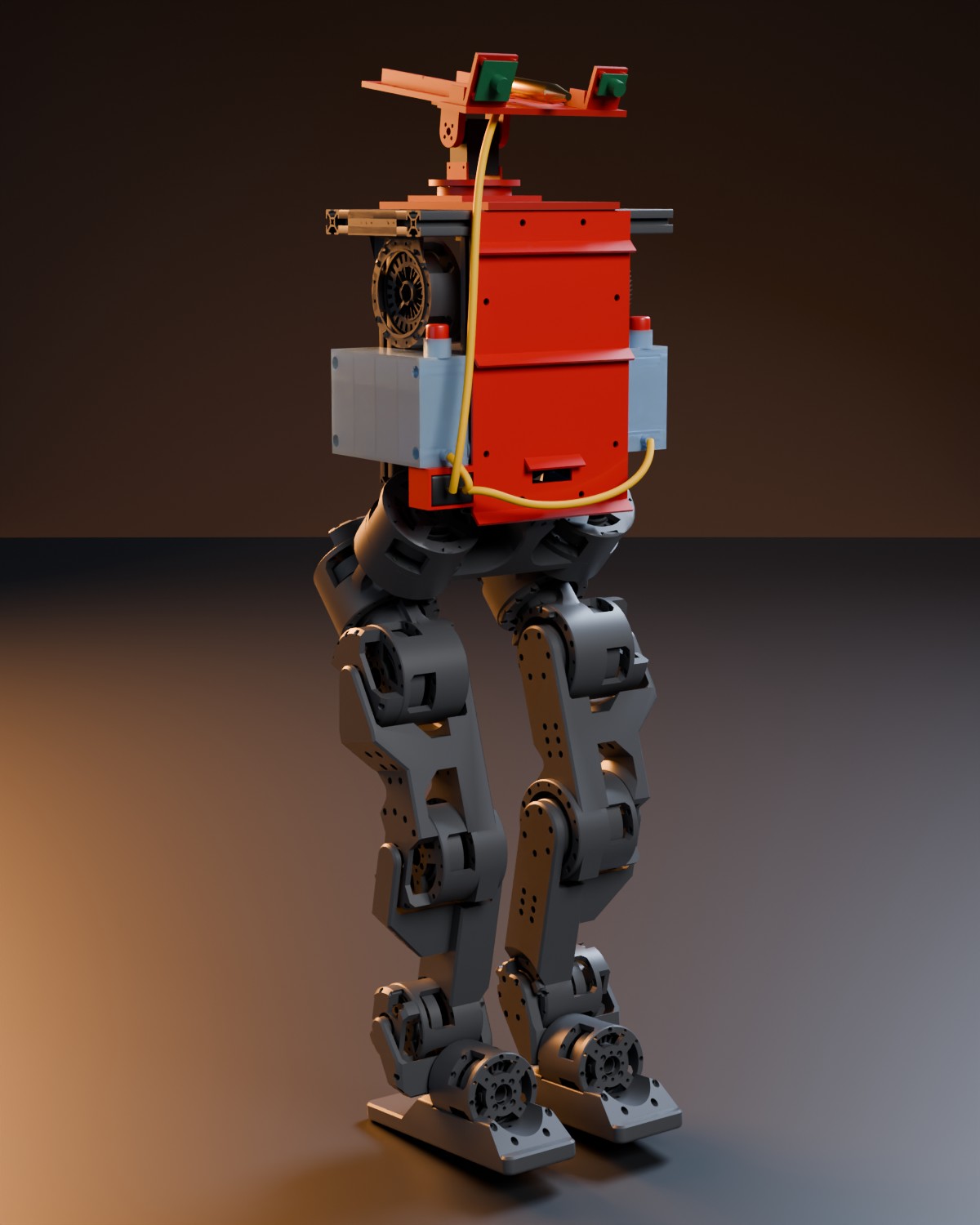
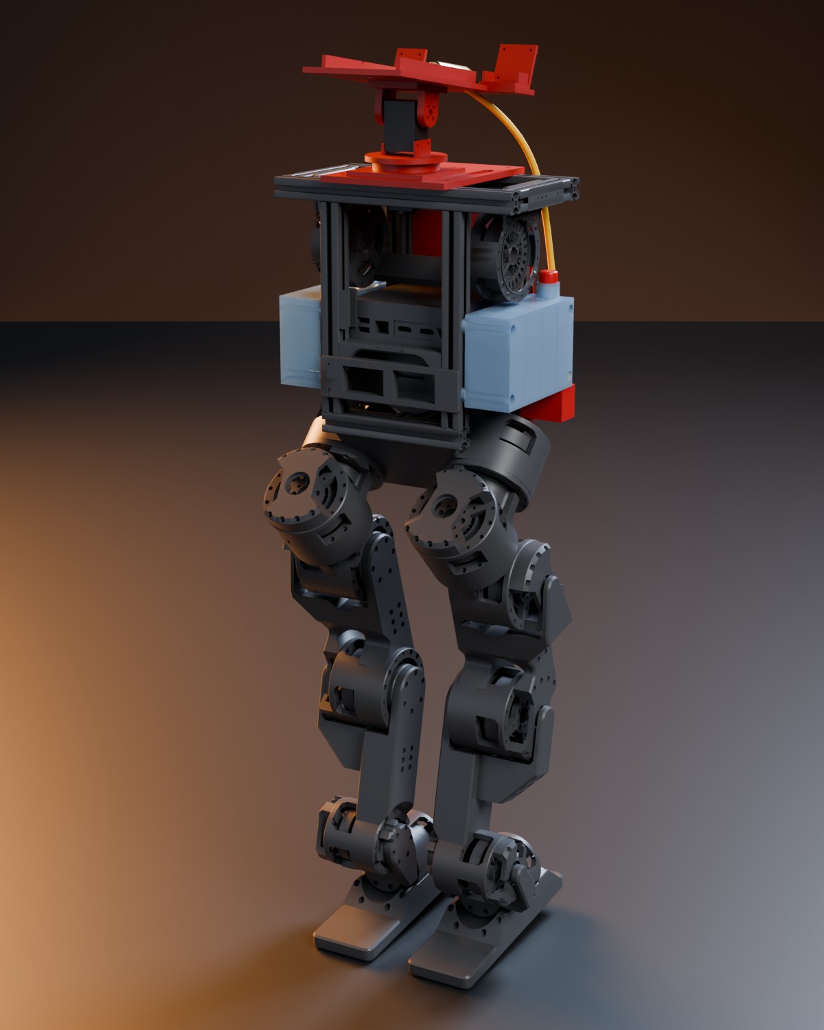
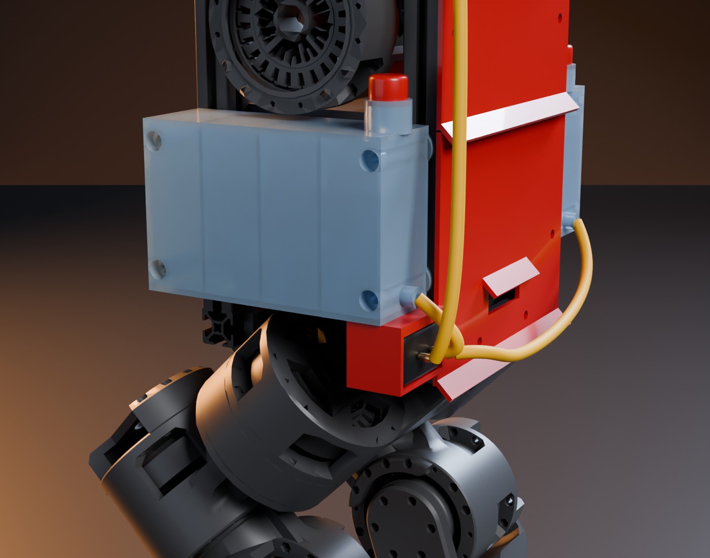
- Each tank is x ±66 mm and y 78 to 124 mm from the centre line, 113 to 199 mm under the frame top. The right tank is the mirror of the left one.
- A pocket in the inner face clears the end of the battery. Both tanks have it, so one design prints twice, mirrored.
- The tanks hold 0.725 L together. Each has 3 baffles across x.
- Four M5 × 55 screws per tank go through closed tubes in the tank into drop-in T-nuts in the side slot of the posts. Pads on the inner face touch the posts.
- No space inside the torso is lower than the water. So the pump sits in a printed holder in front of the right hip, below both tank floors. The left tank feeds it through a tube across the front of the torso.
Simulation results tested in simulation
Balance and leg torque
We used the same slow poses as in the earlier payload rounds: standing, crouching and standing on one leg. One-leg stance happens in every step. The walking policy was trained with a 6 Nm torque limit.
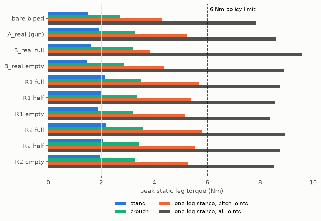
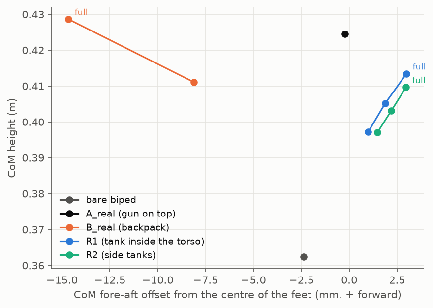
- R1 and R2 lower the robot centre of mass by 12 to 19 mm compared with A_real and B_real.
- The one-leg pitch torque is 5.7 Nm (R1) and 5.8 Nm (R2), below 6 Nm. It is 0.5 Nm more than A_real, because the mass sits 3 mm further forward.
- The backpack is still the best for this torque (3.9 Nm), because its water pulls the centre of mass back. The fore-aft position matters more than the height.
Walking and pushes
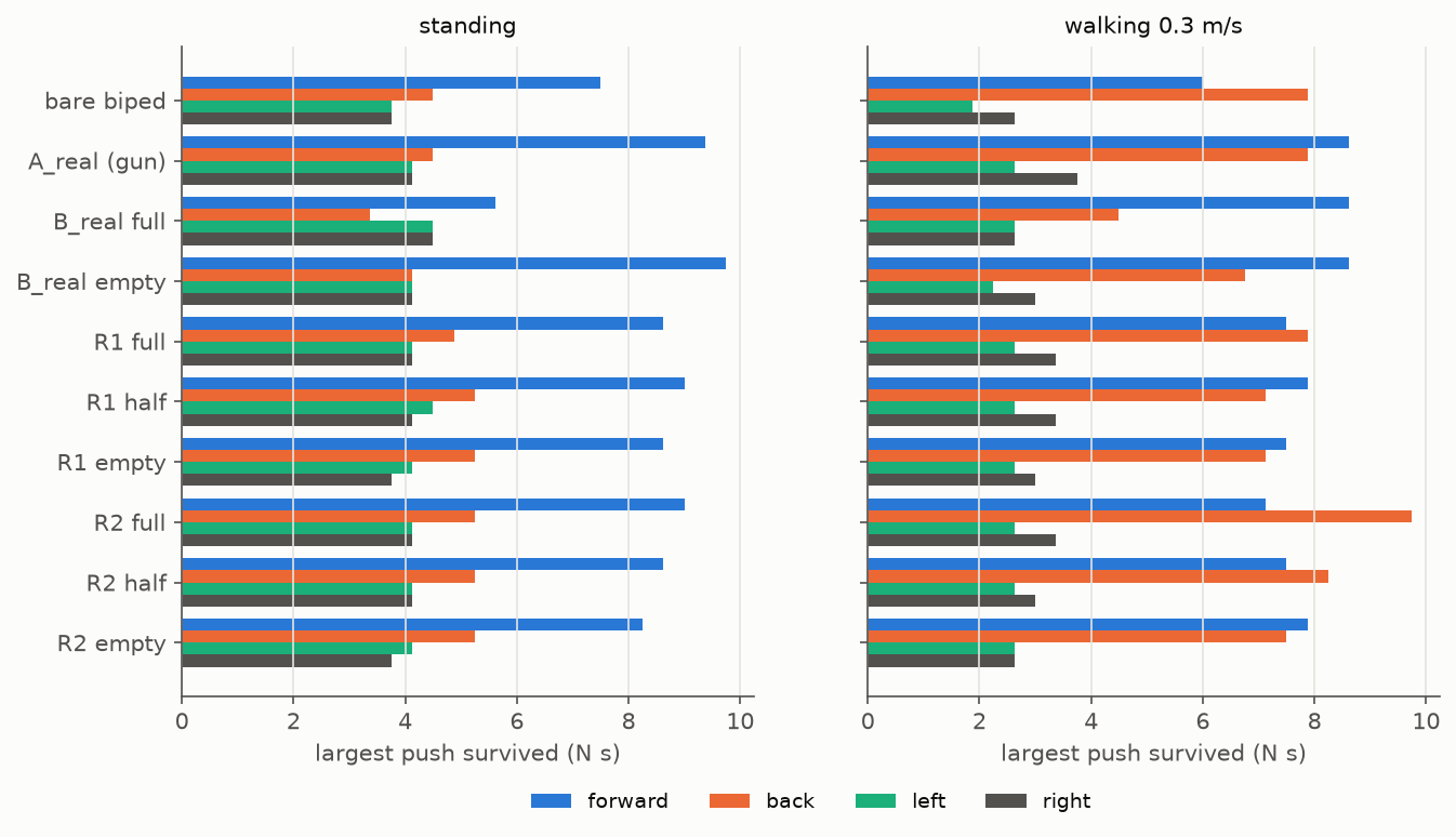
We ran the shipped Berkeley walking policy in our MuJoCo loop, with the training sensor noise. For the push test, a force acts on the torso for 0.1 s while the robot stands or walks at 0.3 m/s. A search finds the largest push with no fall in the next 3 s. The push comes at three gait phases, and the table keeps the worst.
- At 6 Nm, R1 and R2 walk at 0.29 to 0.30 m/s for a 0.30 m/s command and turn at 0.47 to 0.53 rad/s, like the bare robot. The full backpack reaches only 0.20 m/s.
- At 4 Nm, R1 and R2 with full tanks fall in some walking runs, like A_real and B_real. We still need 6 Nm.
- R1 and R2 stay within 1.5 N s of A_real in every push direction. Against a backward push while walking, R1 survives 7.9 N s and R2 9.8 N s. The full backpack survives only 4.5 N s.
| Model | Standing: forward | back | left | right | Walking: forward | back | left | right |
|---|---|---|---|---|---|---|---|---|
| bare robot | 7.5 | 4.5 | 3.8 | 3.8 | 6.0 | 7.9 | 1.9 | 2.6 |
| A_real | 9.4 | 4.5 | 4.1 | 4.1 | 8.6 | 7.9 | 2.6 | 3.8 |
| B_real, full | 5.6 | 3.4 | 4.5 | 4.5 | 8.6 | 4.5 | 2.6 | 2.6 |
| R1, full | 8.6 | 4.9 | 4.1 | 4.1 | 7.5 | 7.9 | 2.6 | 3.4 |
| R1, half | 9.0 | 5.2 | 4.5 | 4.1 | 7.9 | 7.1 | 2.6 | 3.4 |
| R2, full | 9.0 | 5.2 | 4.1 | 4.1 | 7.1 | 9.8 | 2.6 | 3.4 |
| R2, half | 8.6 | 5.2 | 4.1 | 4.1 | 7.5 | 8.2 | 2.6 | 3.0 |
In the MuJoCo videos, the red and blue boxes stand for the masses of the added parts.
Water slosh
Water in a part-full tank moves. We modelled the first sloshing mode of each tank as a mass on springs, with the standard model for a rectangular tank (NASA SP-106). The worst case is a half-full tank.
| Half-full tank | Slosh share of the water | Frequency fore-aft / sideways | Peak travel while walking and turning |
|---|---|---|---|
| R1, no baffles | 71 % | 2.0 / 1.9 Hz | 31 / 33 mm |
| R1, CAD baffles | 39 % | 5.1 / 4.3 Hz | 8 / 10 mm |
| R2, no baffles | 60 % | 2.2 / 4.4 Hz | 24 / 7 mm |
| R2, CAD baffles | 24 % | 5.0 / 4.4 Hz | 3 / 3 mm |
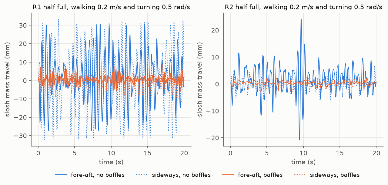
- Without baffles, 71 % of the water in a half-full R1 sloshes at about 2 Hz, near the step rate of the gait.
- The baffles in the CAD raise the slosh frequency to 4 to 5 Hz and reduce the peak travel by a factor of 2 to 10.
- At 6 Nm, slosh did not change any push result by more than one search step. Keep the baffles: they cost almost nothing.
Jet
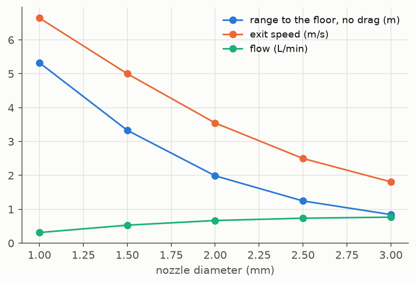
We assumed a straight-line pump curve between the two data points, then took off the lift to the nozzle (0.2 m) and the friction in 0.6 m of 3.2 mm tube.
| Nozzle | Flow | Exit speed | Range to the floor, no drag | Spray time, R1 full |
|---|---|---|---|---|
| 1.0 mm | 0.31 L/min | 6.6 m/s | 5.3 m | 2.0 min |
| 1.5 mm | 0.53 L/min | 5.0 m/s | 3.3 m | 1.2 min |
| 2.0 mm | 0.67 L/min | 3.5 m/s | 2.0 m | 0.9 min |
| 3.0 mm | 0.77 L/min | 1.8 m/s | 0.8 m | 0.8 min |
- Use a 1.0 to 1.5 mm nozzle. A wider nozzle gives more water but a much shorter jet.
- The real range is shorter, because of air drag and jet break-up. The robot must get within about 2 m of the fire.
- The backpack pump gave about 13.6 m/s. This pump trades jet speed for 33 g and 0.5 A.
Hardware review
What to check on the robot
Measure from the top face of the torso frame (the 2020 top rails) downward. Compare with the CAD values.
- For R1, the space above the mini PC must be free down to 110 mm under the frame top. The tank floor is 77 mm under the top, and the pump tray reaches 109.5 mm.
- For R1, the free width between the side parts of the upper torso must be at least 126 mm (y ±63 mm), and the free length between the top rails at least 96 mm.
- For R1, check where the USB board and the cables sit. The CAD has the board at the front, 80 to 106 mm under the top, and a cable channel at the front right.
- For R1, check that the pan base and pan servo hang no more than 29 mm under the deck.
- For R2, the side faces of the posts must be free from 113 to 199 mm under the frame top, with free T-nut slots at 124 and 188 mm.
- For R2, check how far the battery end sticks out of the left side. The CAD pocket clears 89 mm from the centre line.
- Confirm the pump part number and its port layout. The CAD assumes the M400K-V with both ports on one end.
Printed parts
PETG at 1.27 g/cm³, printed solid (100 % infill or 6 perimeters), so that the walls hold water. Wall 2.5 mm, baffles 2.0 mm.
| Part | Print pieces | Mass (g) | Size (mm) |
|---|---|---|---|
| R1 tank | two halves, cut at y = 0, 139 g and 132 g | 271 | 140 × 126 × 110 |
| R1 deck (replaces the deck of the pan-tilt) | one, flat | ≈ 91 at the deck settings | 158 × 130 × 6 |
| R2 tank, each | tub 133 g and inner plate 33 g | 167 | 141 × 49 × 100 |
| R2 pump holder | one | 20 | 28 × 45 × 32 |
| Option | Water | Empty system | Full system |
|---|---|---|---|
| R1 | 0.632 L | 0.349 kg | 0.981 kg |
| R2 | 0.725 L | 0.526 kg | 1.251 kg |
Bought parts
| Item | R1 | R2 | Note |
|---|---|---|---|
| TCS M400K-V pump | 1 | 1 | Or the part the team ordered |
| Brass hose barb, M5 thread, for 3.2 mm bore tubing | 1 | 2 | Tank outlets. Use thread sealant. |
| Silicone tubing, 3.2 mm bore | ≈ 0.6 m | ≈ 1 m | Pump feed and jet hose |
| Tee for 3.2 mm tubing | – | 1 | Joins the two tanks |
| Tapered silicone stopper | 1 for a 19 mm bore | 2 for a 16 mm bore | Drill a small vent hole |
| M4 heat-set insert (M4 × 8.1, hole 5.6 mm) and M4 screw through the deck | 4 | – | Screw length: deck 6 mm plus the insert depth |
| M5 × 55 screw, washer, drop-in T-nut for 2020 | – | 8 | Into the side slots of the posts |
| Two-part epoxy | yes | yes | Joins the print pieces |
| Drain tube, 6 mm | ≈ 0.3 m | – | From the drip tray out of the torso |
Print and assembly
- Print the R1 halves on their cut face. The notch for the pan base is a 27 mm bridge in this orientation. Use supports there if your printer sags.
- Glue the R1 halves with epoxy along the cut face. The baffles are cut in half too, so they glue at the same time.
- Print the R2 tubs on their outer face, and the inner plates flat. Glue each plate on its tub with epoxy.
- Fill each tank with water and let it stand for one hour on paper. If it leaks, coat the inside with thin epoxy and test again.
- R1: press the four M4 inserts into the pillars. Tap the outlet M5 and screw in the barb with thread sealant.
- R1: put the pump in the tray and connect the outlet barb to the pump inlet with a short tube. Lower the tank into the torso from the top. Bolt the deck to the rails and the tank under the deck.
- R2: drop eight M5 T-nuts into the side slots of the posts. Bolt each tank with four M5 × 55 screws.
- Fill the tank and wait until water reaches the pump before you switch it on. Check the TCS manual for dry running.
Downloads
torso_tank_cad.zip holds the STEP and STL files of every printed part, the assembled tanks, simple blocks for the pump, the check log and the CAD notes. All parts are drawn in the robot frame in mm, so the STL files stack on the robot without a transform.
| File | What |
|---|---|
r1_half_left, r1_half_right | R1 print pieces |
r1_tank | R1 assembled, for fit checks |
r1_deck | Deck of the pan-tilt with the four tank holes |
r2_tub, r2_inner_plate | R2 print pieces (left tank; mirror them for the right tank) |
r2_tank_left, r2_tank_right | R2 assembled, for fit checks |
r2_pump_holder | Pump holder for R2 |
ref_pump_r1, ref_pump_r2 | 40 × 26 × 25 mm blocks where the pump sits |
Recommendation
- Choose R1 if the pump must be inside the torso. It feeds the pump by gravity, needs no knee limit, adds no width, and keeps the tank inside the frame.
- Before R1 goes in the robot, leak-test it, add a splash cover over the mini PC and route the drip tray drain out of the torso.
- Choose R2 if water above the computer is not acceptable. It needs the 1.4 rad knee limit, a pump outside the torso and a tube across the front.
- Order a 1.0 mm and a 1.5 mm nozzle, and measure the jet speed before the first fire test.